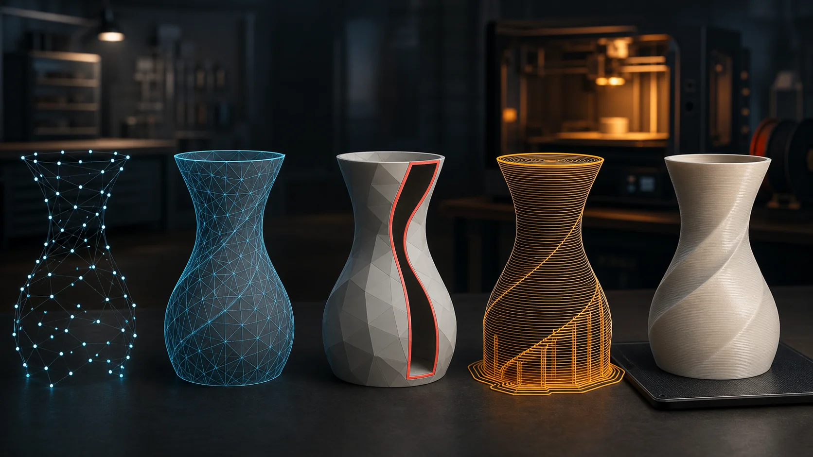
The source mesh, the editable production mesh, and the printable manufacturing package are related objects—not the same object saved repeatedly. A healthy pipeline keeps each representation long enough to compare it with the next.
The ContractDecide What Must Survive
Write down invariants before the first destructive operation: real dimensions, silhouette, named components, UVs, material channels, sharp boundaries, minimum feature sizes, symmetry, rig landmarks, and licensing provenance. A voxel remesh may preserve volume but discard UVs. A decimator may preserve silhouette while collapsing a functional hole.
The CheckpointsKeep Three Masters
- Evidence master: untouched generated, scanned, or authored source with prompt and camera metadata.
- Geometry master: repaired, consistently oriented, editable surface with materials and history.
- Manufacturing master: scaled solid, printer-aware tolerances, component layout, and validated export.
The PipelineMeasure Before Repairing
Inventory components, bounds, units, triangle quality, boundary loops, nonmanifold edges, self-intersections, normals, thickness, and attributes. Repair only after you know which failures are structural and which are intentional open surfaces.
Then establish units, make a solid if manufacturing requires one, enforce feature thickness, choose orientation, preview support and slice paths, and render several diagnostic angles. The slicer is a second geometry engine; examine its output rather than treating export as the finish line.
A Small ManifestMake the Chain Reproducible
{
  "source": {"asset": "concept-v7.glb", "sha256": "...", "units": "m"},
  "geometry": {
    "repair": ["orient_faces", "close_small_holes"],
    "target_size_mm": [84, 61, 112],
    "minimum_wall_mm": 1.2
  },
  "print": {
    "process": "FDM", "nozzle_mm": 0.4,
    "layer_mm": 0.2, "material": "PETG",
    "orientation_quaternion": [0, 0, 0, 1]
  },
  "checks": {"watertight": true, "self_intersections": 0}
}
File StrategyUse Formats for What They Know
GLB is strong for compact preview geometry and PBR appearance. OBJ remains useful for broad interchange but has weak manufacturing semantics. STL carries triangle geometry and little else. 3MF is designed for manufacturing packages and can represent units, components, materials, properties, slices, and extensions without reducing the job to anonymous triangles.